If you read the difference between the main bar and distribution bar post, then this will be easy to understand.
As mentioned in that post, take the same example of a wooden writing pad.

Support the wooden pad at both ends. Now apply force on the top middle of the pad. You can observe the deflection below the pad. The pad bends at the centre and rises at the support.
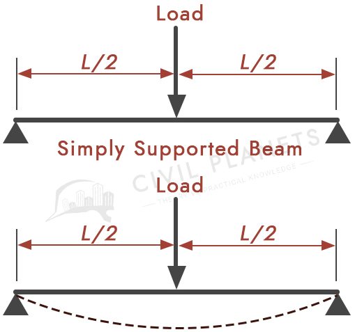
What you’ve seen is the typical slab load handling scenario.
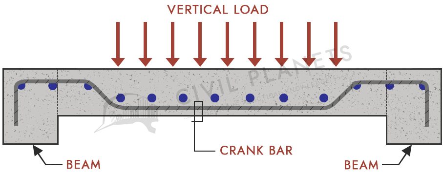
As you can see from the pic, the stress will deflect the beam at the bottom centre. This incident creates a positive moment (sagging) at the mid of the base and negative moment (Hogging) at the top of the support.
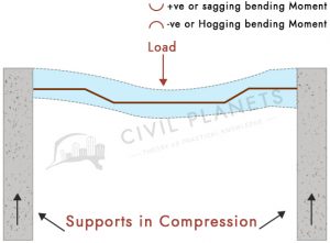
- Bottom reinforcement bars are provided to resist the positive (sagging) moment developed in reinforced concrete.
- To withstand the negative moment (hogging), and shear stress, top reinforcement bars (crank bars) are provided near the support as shown in the pic.
Crank bars are provided to make the steel available at both top and bottom reinforcement. Since the steel is required only where the positive and negative moments are created, crank rods are provided in such a way that the same steel bar can be used for both positive (mid of the slab) and negative moment area (end supports).
Reasons
Crank rods are provided for the following reasons.
- To save cost
- For economical usage of steel
- To avoid the risk of brittle failure
- To resist the sagging and hogging by single steel reinforcement
- To withstand the shear stress developed at the end support
Crank Bars Specification
- Only alternate bars will be cranked.
- Crank bars are provided at the slope of 1:10.
- Crank bars will be provided for at least 300 mm length.
- Crank bars will be provided at different angles such as 45° or 30° based on the beam depth.
Happy Learning 🙂